USB Serial Monitor
from KEUWLSOFT
Currently not available on app stores. Can be downloaded at Buy Me a Coffee (coffee optional).
Supporters on Patreon can find the app here .

USB Serial Monitor
For the hobbyist, connect to USB-Serial devices and send/monitor serial data. Connect to devices containing USB-Serial chips such as FTDI, Mega16u2, CH340, CP210x and PL230x.
• Adjust connection settings such as baud rate, data bits, polarity and stop bits.
• ASCII and Hex display formats.
• Save data to file.
• 6 Memory buttons for send strings.
• Option to enter data as Hexadecimal.
• Results screen to show technical details of connected USB devices.
Send up to 256 characters at a time. Monitor will display up to 10000 lines.
Some Screenshots:
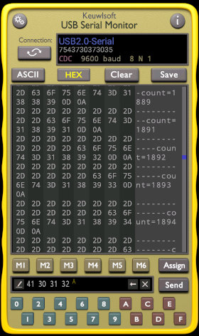
Hex Mode |

ASCII Mode |

Connection Settings |
App Guide:
This app allows you to send and receive serial data over the USB to a device with a suitable USB-Serial USB chip such as FTDI, Mega16u2, CH340, CP210x and PL230x.
Getting started quickly
1) After running the app, you will first need to connect to your device, Tap the change connection button near the top of the screen.
2) Connect your USB device using a suitable USB OTG(On-The-Go) cable if needed, and allow the app to access the USB device if a pop up appears.
3) In the set-up connection screen, tap Find USB devices. Any connected USB devices will be shown in a list. Select your device.
4) Change any connection settings such as baud rate to match those of your connected device. Leave the method/chipset on auto as in most cases the correct protocol is detected.
5) Tap Connect. You will return to the main screen and see the connected device in the upper connection window.
6) Tap the lower send window to open up a dialog to edit its contents. Tap send to send it over the USB Serial link.
7) Tap the ASCII/Hex to change the monitor format. The 16 hex buttons can be used to enter in hexadecimal values.
8) The Assign button can be used to store the send window contents into any of the 6 memory buttons.
9) The send and received data is shown in the main window, and can be scrolled, Cleared or Saved.
More detail follows:
USB Host and USB OTG
To use this app, your device will need USB Host Capability. One way to check this is just to plug something in and try to connect, by tapping Find USB devices in the connection screen.If no USB devices are detected: Try re-clicking Find USB devices. Try plugging in a different USB device. Try stopping and running the App again. Check USB OTG cable for a good connection. Note that not all devices have USB Host capability.
To connect to an external device you may need an On-The-Go (OTG) cable to plug into the USB port of your Android device. At the other end of the OTG cable will be one (or more) full size USB sockets in which USB cables can be plugged in linking directly to your project.
USB to Serial Chip
To communicate over the serial usb connection, your project will need a chip capable of usb to serial conversion. Most development boards have USB to serial built in, for example the Arduino UNO has a ATmega16u2 USB to serial chip included on the board.If not built in or if extra USB to serial connections are required, USB to serial breakout boards can be used. These breakout boards all have RX, TX, GND and Voltage connections, and possible extra connections for a second voltage or flow control. The connection arrangement will vary between these boards. The USB to Serial chips also have different protocols of how the USB is configured to allow for serial communication. Therefore, whilst most USB to Serial devices used in hobby electronics (e.g. those in image below) will work with this app, there may be some USB-serial devices that wont work.
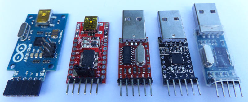
Mega16u2, FTDI, CH340, CP2102 and PL2303 USB to Serial Breakout boards.
Connection Settings
If not done already, on the USB connection screen, with your USB device plugged in, tap Find Devices. The app will discover any attached USB devices and list them. Select your device. The following connection options will now be enabled from which the USB-Serial connection protocol can be tweaked. The options available will depend on what has been connected and the chip/method it uses.Interface - Within each usb device, there are multiple interfaces, some of which have bulk transfer in and out end points that are used in serial communication. Only these interfaces can be selected for connecting to. The app will automatically select the most appropriate interface with suitable endpoints for serial communication.
Chip / Method - Manufacturers implement serial communication through USB a little differently. Serial communication without flow control has been implemented for a range of usb to serial chips. The app will automatically suggest the appropriate chip/method to use based on the vendor of the chipset determined from the USB scan.
The following settings may not be available to all chip/methods:
Baud Rate - The baud rate can be set at a range of speeds from 300 up to 921600 bps. Make sure it matches that set in your project. Suggest starting always at 9600 baud, 8 Data Bits, No Parity and 1 stop bits, and then go on from there.
Data Bits - Set the number of data bits to use as 5, 6, 7 or 8.
Parity - Set Parity to None, Odd, Even, Mark or Space.
Stop Bits - Set Stop bits to 1, 1.5 or 2.
Connect and Disconnect
Once a compatible USB device is selected, and any settings changed as necessary, we can click Connect. Once connected, you will be returned to the main screen.Auto connect is enabled by default in the settings. In this case, after successfully connecting to a USB device, the most recent connection will be remembered so that next time the app is run and the same device connected, it will connect automatically with the same settings. Just tap the change connection to change the connection settings or USB device again.
To disconnect, either tap Disconnect, connect to another device, pull the usb cable out or close the app.
Results
After discovering any attached USB devices, tapping Results will open up a detailed list of the properties of the discovered devices. This information is only there for those interested/curious, and can be copied to the clipboard ready for pasting in another application if required.If USB devices are detected, details reported include:
• Device Serial Number
• Vendor ID
• Product ID
• Manufacturer String Descriptor
• Product String Descriptor
• Class, Subclass and Protocol
• USB Version
• Max Power
• Number of Configurations
• Number of Interfaces
• Interface and Endpoint Info
Note the amount of info shown will depend on the USB device and the amount of access allowed.
Each USB device can have multiple configurations, but rarely more than one is used. Within each configuration, a USB device can have up to 16 interfaces. Each interface can have its own class, subclass and protocol and is used for a particular task of the USB device functionality. Within each interface there can be multiple Endpoints on which data can be sent to or from the USB device.
The top level USB classes are defined as:
| Class | Device Type |
| 1 | Audio Device |
| 2 | Communication Device |
| 3 | HID Device |
| 5 | Physical Device |
| 6 | Still Imaging Device |
| 7 | Printer Device |
| 8 | Mass Storage Device |
| 10 | Communication Data Device |
| 11 | Smart Card Device |
| 13 | Content Security Device |
| 14 | Video Device |
| 15 | Personal Healthcare Device |
| 16 | Audio/Video Device |
| 17 | Billboard Device |
| 18 | USB Type-C Bridge Device |
| 220 | Diagnostic Device |
| 224 | Wireless Controller Device |
| 239 | Miscellaneous Device |
| 254 | Application Specific Device |
| 255 | Vendor Specific Device |
Subclasses and Protocol values depend on the Class.
Vendor ID and Product ID are 16 bit unsigned integer values identifying the device.
Serial Number, Manufacture String and Product String are optional. Not all devices will use them, but if they do you will get
a more friendly description of the device.
USB version is that of the attached USB device.
Max Power gives the maximum current draw that the device might need so that the OS can decide whether to accept it. The actual power used
will vary and is determined in other ways.
Other information such as endpoints and their direction will give an indication of how the device achieves is functionality.
ASCII & Hex Monitor
The main window show the monitored sent and received data. The monitor can handle up to 10000 lines of ASCII data, after which, the data window needs to be cleared again, in order for it to receive more data.The ASCII format just shows the ASCII data, with a new line started each time a line feed character is received, the data overflows the line length, or the data type changes from sent to received or visa versa. Sent data is shown in blue, and received in white. The monitor window can be set to just show received data in the settings screen.
In the Hex mode, each ASCII line is split into upto 4 Hex lines, each showing the Hexadecimal equivalent of upto 8 ASCII characters. The ASCII is also repeated on the right of the display.
Editing the Send String
The send string is up to 256 bytes/characters long. Inn ASCII mode, an ASCII string is edited. In hex mode, bytes in hexadecimal format are edited.The Delete key at the right of the send window will delete the last character/byte. The X will clear the send window contents.
Tapping on the Edit icon or anywhere else in this window will open up a dialog where the keyboard can be used to enter the string. In hex mode, you will have to enter the data in space separated hexadecimal bytes. Change the ASCII/Hex mode prior to editing the send string contents if required.
Hex Buttons
These buttons allow you to quickly enter hex into the send string window. Each byte or ASCII character requires two hexadecimal digits, so the first one will be shown smaller in a different color until the second digit is inputted. Only after each two digit input will a new byte/character be added to the send string.Memory Buttons
There are 6 memory buttons labelled M1 to M6. Tap the Assign button followed by one of the memory buttons M1-M6, to assign the contents of the send window to a button.Once something has been assigned to a memory button, it can be made to either send that string over the USB-Serial connection, or recall it back to the send string window, ready for further modification before sending with the Send button. Whether the memory buttons send or recall can be set in the settings screen.
Save
To save the data, tap the Save button. Saving requires write storage permission, so you may my requested for this permission first. A dialog will then appear, allowing you to edit the filename. The saved files will be placed in a keuwlsoft\usb-serial\ directory in the documents folder on your device. For earlier app versions the keuwlsoft/usb-serial directory was found in the root directory.The data can either be saved as formatted (as is seen in the monitor window), or as raw received. If the formatted option is chosen, the saved data is an ASCII text file corresponding to the contents of the monitor window which will be different depending on whether ASCII or Hex mode is currently shown. If the raw received option is chosen, the data is stored as it was received with no extra formatting and no sent strings, but still as an ASCII text file.
Settings
Sound On - Toggles sound on or off.
Vibrate On - Toggles vibrate effects on or off.
Stay Awake - Check this option to stop the device from sleeping.
Auto Connect - The most recent successfully connected USB device, if it is detected, will automatically be connected to when
the app is run.
Monitor Display - Set this to show either just the received data, or both the sent and received data.
Memory Button Operation - The memory buttons by default, just send their contents immediately on the USB-Serial connection. If this
is set to recall, then their contents are copied to the send string window. In this case, they can be modified if required before using the send button.
Reset Defaults - Resets the default settings.