
Remote Sounds
Prank or tease your friends and family with unique sounds you have recorded on a ISD1820 module. Remotely activate those sounds at the right time.
This demo uses the IR Remote Creator App
and the JVC Infrared Protocol to communicate to an IR module attached to an Arduino which in turn controls a ISD1820 module for recording and playing back sounds.
IR Remote
This example makes use of the IR Remote Creator App, where a remote with 5 buttons has been designed to work with the Arduino code on this page.

ISD1820 Controller Remote for this Demo
Get the remote for this demo in one of these ways:
1) If you are accessing this page from a device with the app installed, then tap here to load it into the App.
2) Alternatively download isd1820controller.txt into the keuwlsoft/ir-remotes/ directory in the documents folder on your Android device, and then load it from within the app.
3) Alternatively, in the load from web link option within the app, enter: https://www.keuwl.com/ir-remotes/isd1820controller.txt
JVC InfraRed Protocol
The remote for this demo uses the JVC InfraRed Protocol. This protocol pulse distance modulation on a carrier wave that is typically 38 kHz. The distance between pulses is used to differentiate a 0 or 1.
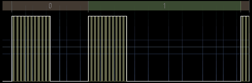
Pulse Distance Modulation
The IR pattern comprises a header pulse, 16 bits of information, and then a stop or end bit. The 16 bits of data are split into an 8 bit address and an 8 bit command.
The address decides the target device of the IR transmission whilst the command determines the function on that device.
For all 5 buttons, the address being used for this demo project is zero. If changing the address of the sent data, make sure the Arduino code is adjusted to match. For example, If you have multiple IR projects, you can assign them different addresses so that the signal is only received by the one that should receive it.
As an example of an IR pattern, the pattern for the REC button on the remote is shown below.
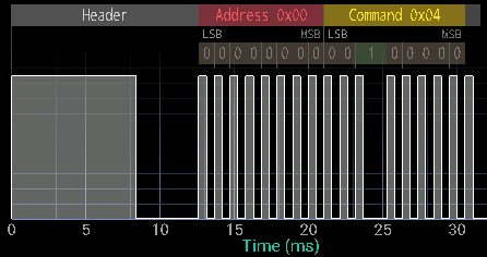
IR pattern for the REC Button
For the buttons, we have used command numbers 1 to 5 (0x01 to 0x05 hex). Thus the code table for the remote is:
| Button | Address | Command |
| PLAYE | 0x00 | 0x01 |
| PLAYL | 0x00 | 0x02 |
| PLAYL Stop | 0x00 | 0x03 |
| REC | 0x00 | 0x04 |
| REC Stop | 0x00 | 0x05 |
There is nothing special about this choice of command numbers. Change them if required and update the Arduino code to match.
ISD1820 Module

ISD1820 Module
The ISD1820 Module comes in a variety of forms, although all function more or less the same. They can be bought together with a speaker for a few dollars. On the board is the ISD1820 chip,a microphone and 3 buttons. The buttons are REC, PLAYE and PLAYL. These buttons can be used to record sounds with the miocrophone and play them back.
The module has VCC and GND connections for power (typically 3.3V), An output connector for a speaker to be attached. Once powered, and a speaker connected, the module could be used as it is with the 3 buttons and no further connections.
REC - Pressing and holding this button will cause the microphone to record for up to 8-20 seconds (depending on how the ISD1820 has been configured). Recording stops when the maximum length of recording is reached, or when the REC button is released.
PLAYE- Pressing this button will cause the complete playback of the repeated sound. This button does not have to be held down.
PLAYL - Plays the recording back only whilst the PLAYL buttons is pressed.
There are digital lines corresponding to the three buttons, such that the Arduino can be used to control the REC, PLAYE and PLAYL functions with 3 digital outputs. Thus with the IR module, we can perform any of the functions remotely. To simulate the long press of the REC and PLAYL buttons, the remote has split them into start (button press) and stop (button releases) buttons.
Components used
- Arduino Uno
- TSOP4838 InfraRed Receiver Module
- ISD1820 module with Speaker
Circuit Diagram
The TSOP4838 IR Receiver Module can be plugged straight into the Arduino board using pins 2 through 4, avoiding the need for extra wires or breadboard. This is because the module only draws a few mA at most, which can be supplied from the digital output pins. In this case pin 3 is set to LOW, and pin 4 set to HIGH in order to supply power to the IR module. Alternatively, provide a GND and Vcc connection in the usual way to free up those pins again.

Whilst we are using an Arduino Uno for this demo, you could use a different model if you prefer, just make sure the IR receiver module output is to an external interrupt pin.
The TSOP4838 InfraRed Receiver Module has 3 connections, GND, 5V, and OUT. For other Receiver Modules, see datasheet to get the correct connections etc.
Arduino code
Open the Arduino software, select the correct COM Port and Arduino device in the Tools menu, copy and paste the sketch below and click upload.
Of note in this sketch is the way it handles the incomming IR pattern data. Rather than tieing up the main loop and constantly monitoring the IR signal, we have used interrupts instead. This leaves the main loop free to carry out other important tasks.
The interrupt is called every time the external interrupt pin changes state. It logs the elapsed micros() time of the Arduino, and then resumes from where it was before. Once IR pattern data has been collected and a pause is observed at the end of the pattern, it's analysis is done in the main loop.
Once new IR command has been received, a switch-case is used to run code for that command.
The clear_isd1820() function, along with the recording and playing flags are used to make sure the REC and PLAYL lines have gone LOW before another button press is simulated.
// Control a ISD1820 module by remote using Arduino and a TSOP4838 IR Receiver module
// By keuwlsoft:  www.keuwl.com  4th Apr 2019
// cc Attribution-ShareAlike
//
// This sketch will receive an IR Pattern, Decode the Address and Command (JVC Protocol).
// Then if data valid and address matches, will use a switch case to action the command.
// Controls a ISD1820 module using Arduino pins 8 to 10 which connect to the PLAYE, PLAYL and REC.
// The TSOP4838 IR module is plugged straight into pins 2 to 4, using pins 3 and 4 to power it.
// An Interrupt is used to gather the IR Pattern timing, which is later analysed, thus keeping the main loop free for other tasks.
// Keuwlsofts 'IR Remote Creator' App was used to send the IR signal.
// The Remote and explanation can be found at www.keuwl.com/electronics/rduino/ir/04-remote-sounds/

int ir_pin=2; //use pins 2 or 3 for external interrupts, connect the IR receiver module output here.
int gnd_pin=3; //ground pin for the TSOP4838
int vcc_pin=4; //vcc pin for the TSOP4838
int playe_pin=8;
int playl_pin=9;
int rec_pin=10;

boolean recording=false; //flag to indicate if IRD1820 currently recording sound
boolean playing=false; //flag to indicate if IRD1820 currently playing sound with PLAYL method

long no_change_time=10000; //No change in IR pin for this duration (microseconds) will mark the end of pattern.
const int array_size=100; //Max times to log.  If array is full, it will report the pattern to that point.
long t_array[array_size]; //Array of times of when the IR pin changes state.
int count=0; // Number of times logged to array.
boolean log_micros=true;  //Flag to indicate if able to log times to array
long last_micros=0; //previous array time entry

int addr=0; //Device address decoded from IR pattern
int cmmd=0; //Command decoded from IR pattern
int our_device_addr=0; //integer (0-255) that is an address to identify our device amoungst other devices.
boolean new_data=false; //Flag that is set everytime a new IR command is received


void setup() {
  pinMode(ir_pin, INPUT);

  //attach an interupt to log when the IR pin changes state
  attachInterrupt(digitalPinToInterrupt(ir_pin),interupt,CHANGE);

  //Supply power to TSOP4838 (Uses upto approx 1.5mA)
    pinMode(gnd_pin, OUTPUT);
    pinMode(vcc_pin, OUTPUT);
    digitalWrite(gnd_pin,LOW);
    digitalWrite(vcc_pin,HIGH);

 //Set pins connected to the IRD1820 board as outputs
    pinMode(playe_pin, OUTPUT);
    pinMode(playl_pin, OUTPUT);
    pinMode(rec_pin, OUTPUT);

}

void loop() {

//=========================================== Extract IR Command
  if (count>0){
    if (!log_micros|((micros()-last_micros)>no_change_time)){
      log_micros=false; //make sure array not modified while we analyse it
      //Get Pattern
      count--;
      for (int i=0;i<count;i++){
        t_array[i]=t_array[i+1]-t_array[i];
      }
      //Extract Command And Address of JVC protocol
      if (count>=32){ //Check patten long enough for 16 bits of data
        int pos=count;
        // Extract Command
        cmmd=0x00;
        for (int i=0;i<8;i++){
          cmmd=cmmd<<1; pos-=2;
          if (t_array[pos]>1000)cmmd=cmmd|1;
        }
        //Extract Address
        addr=0x00;
        for (int i=0;i<8;i++){
          addr=addr<<1; pos-=2;
          if (t_array[pos]>1000)addr=addr|1;
        }
        //check if data was for our device
        if (addr==our_device_addr) new_data=true;
      }

    log_micros=true; count=0; //Reset array so another IR pattern can be received
    }
  }
//===========================================


//=========== Do Something with the Newly Received Command
  if (new_data){
    switch(cmmd){
      case 1: // PLAYE (Play complete recording on ISD1820)
        clear_isd1820(); //clear any current PLAYL or REC operation
        digitalWrite(playe_pin,HIGH);
        delay(10);
        digitalWrite(playe_pin,LOW);
      break;
      case 2: //PLAYL (Start playing recording on ISD1820)
        clear_isd1820(); //clear any current PLAYL or REC operation
        digitalWrite(playl_pin,HIGH);
        playing=true;
      break;
      case 3: //PLAYL (Stop playing recording)
        digitalWrite(playl_pin,LOW);
        playing=false;
     break;
      case 4: //Start recording sound on ISD1820
       clear_isd1820(); //clear any current PLAYL or REC operation
       digitalWrite(rec_pin,HIGH);
       recording=true;
      break;
      case 5: //Stop Recording
        digitalWrite(rec_pin,LOW);
        recording=false;
      break;

      default:
      break;
    }
    new_data=false;
  }
//===========

  delay(10);
}

// clear any current recording/playing operation on the IRD1820 so ready to accept new command
void clear_isd1820(){
  if (recording){
    digitalWrite(rec_pin,LOW);
    recording=false;
    delay(100);
  }
  if (playing){
    digitalWrite(playl_pin,LOW);
    playing=false;
    delay(100);
  }
}


//========================================================
// Interupt to log each time the IR signal changes state
void interupt(){
  if (log_micros){
    long m=micros();
    if (count>0&&(m-last_micros)>no_change_time){
      log_micros=false;
    }else{
       t_array[count]=m;
       count++;
       last_micros=m;
       if (count>=array_size) log_micros=false;
     }
  }
}
//========================================================