
Raw Timing Detector
An IR receiver module is used with an Arduino Uno to listen to an IR transmission and
then report the timings to the serial monitor.
Use
Possible uses of this demo include:
To listen to an IR transmission from any remote and generate a raw timing pattern that can be used to recreate the transmission via the IR Remote Creator App, or from other suitable software/device.
Re-use / upcycle an old remote - Any remote can be used for your Arduino project, you don't need to buy a new one, just find out the IR patterns with this demo, and then code your project to listen out for them.
Find the IR transmission codes for that remote you got for your Arduino project that came with no datasheet, or was in a language you are not familiar.
Serial Monitor
Once the Arduino code on this page is uploaded and run, every time an IR transmission is detected, it will return pattern timing (in microseconds) via the serial connection.
If the Arduino is connected to a computer, then run the Serial Monitor from the Arduino IDE. Otherwise use another suitable serial monitor.

Serial Monitor showing timings returned from Arduino.
The times are shown in pairs with first the HIGH time and then the LOW time. Note that this might be the inverse of the Output from the IR Receiver Module, which may go high when the signal is low and visa versa.
The final time entry is normally a high time, since it timed out waiting for the end of the low time, which would not occur unless another IR transmission is started. This timeout value can be set in the Arduino sketch and determines how long of a pause should decide the end of transmission. If you are looking for the transmission without repeats, 10 or 20 ms is a good value (depends on IR protocol used). If you want to make sure you capture the complete transmission with all repeats, 80 ms or higher might be needed.
The final line, just shows all the times in one long row, which can be copied and pasted to where it is needed. For example, in the IR Remote Creator App, in Editor mode, select the relevant button, enter IR settings, select raw format, and then paste in the pattern. Don't forget to add a final low time if you want to make sure no other transmission occurs at the end of this one for a set period of time.
If pasting into a remote file for use with the IR Remote Creator App, then take caution not to copy newline characters which will cause the file to fail on loading into the app as newline marks the end of an instruction. To assign a raw transmission to a button in the remote file, use the instruction:
transmit_raw(38000,"")
beneath the relevant add_button() instruction. The pattern is pasted into the quotes "". Also change the frequency from 38 kHz if required.
IR Receiver Module
This project used a VS1838B InfraRed Receiver Module. There are a range of IR receiver modules available, the main difference being in the carrier frequency. 38 kHz is by far the most popular frequency for IR remotes, but you will also find 30 kHz, 33 kHz, 36 kHz 40 kHz, 56 kHz and others available. Unless you need a specific frequency to match a particular remote/device, 38 kHz is probably going to be the cheapest and best option. There is some overlap in frequency capability. i.e. expect a 38 kHz receiver to also be able to pick up a 36 kHz signal (for example), but weaker and at a closer range.
Check the datasheet of your IR receiver module so that you connect you device correctly (otherwise it might heat up and burn out and then not work anymore). The IR receivers generally will have three connections: Ground, +V and a Output. Note that the output could be inverted to what you think it is going to be. Checking the data sheet that the IR receiver uses a suitable voltage for your Arduino to supply is probably a good idea too.
The IR receiver packages do all the necessary amplification & demodulation and just output any IR pattern they receive as a digital signal which we will read with the Arduino.
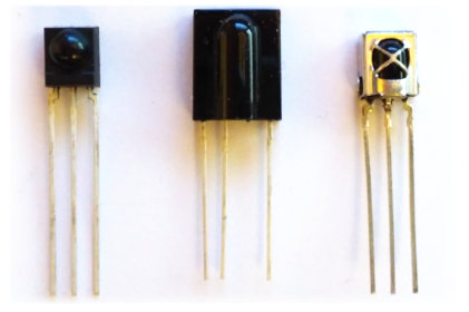
Some IR Receiver Modules (TSOP4838, TSOP31256 and VS1838B).
Components used
- Arduino Uno
- VS1838B InfraRed Receiver Module
Circuit Diagram
Connect the InfraRed Receiver Module to the Arduino as in the circuit diagram below. The output of the receiver module needs to go to pin 2 or 3 of the Arduino as we can enable external interrupts for those pins.

Whilst we are using an Arduino Uno for this demo, you could use a different model if you prefer, just make sure the ir receiver module output is to an external interrupt pin.
The VS1838B InfraRed Receiver Module has 3 connections, GND, 5V, and OUT. For other Receiver Modules, see datasheet to get the correct connections etc.
Arduino code
Open the Arduino software, select the correct COM Port and Arduino device in the Tools menu, copy and paste the sketch below and click upload.
Of note in this sketch is the way it handles the IR pattern data. Rather than tieing up the main loop and constantly monitor the IR signal, we have used interrupts instead. This leaves the main loop free for other important tasks should we choose to modify the code and add some.
The interrupt is called every time the external interrupt pin changes state. It logs the elapsed micros() time of the Arduino, and then resumes from where it was before. Once IR pattern data has been collected and a pause is observed at the end of the pattern, the pattern timings are reported from in the main loop.
// IR Raw Timing Detector
// By keuwlsoft:  www.keuwl.com  16th Feb 2019
// cc Attribution-ShareAlike
//
// This sketch will report the raw timings (in microseconds) from an ir transmission.
// Make sure your IR receiver is of similar carrier frequency to the source.
// Typically, an odd number of times is reported as last Low time is indefinate.


int ir_pin=2; //use pins 2 or 3 for external interupts
long no_change_time=40000; //No change in IR pin for this duration (microseconds) will mark the end of pattern.
const int array_size=300; //Max times to log.  If array is full, it will report the pattern to that point.
long t_array[array_size]; //Array of times of when the IR pin changes state.
int count=0; // Number of times logged to array.

boolean log_micros=true;  //Flag to indicate if able to log times to array
long last_micros=0; //previous array time entry

void setup() {
   pinMode(ir_pin, INPUT);

   //attach an interupt to log when the IR pin changes state
   attachInterrupt(digitalPinToInterrupt(ir_pin),interupt,CHANGE);

  //Initiate Serial for Communication
   Serial.begin(9600);

}

void loop() {

  if (count>0){
    if (!log_micros|((micros()-last_micros)>no_change_time)){
       log_micros=false; //make sure no more data added to array while we report it

       //Convert to durations
       count--;
       for (int i=0;i<count;i++){
         t_array[i]=t_array[i+1]-t_array[i];
         Serial.print(String(i+1)+") "+String(t_array[i])+" us     ");
         if (i%2==1) Serial.println("");
       }

      //Write the ir pattern as one long string
       Serial.println("");
       for (int i=0;i<count;i++){
        Serial.print(String(t_array[i])+" ");
       }
       Serial.println("");

      log_micros=true; count=0; //Reset array
    }
  }


 delay(10);
}


// Interupt to log each time the IR signal changes state
void interupt(){
  if (log_micros){
    long m=micros();
    if (count>0&&(m-last_micros)>no_change_time){
      log_micros=false;
    }else{
       t_array[count]=m;
       count++;
       last_micros=m;
       if (count>=array_size) log_micros=false;
     }
  }
}