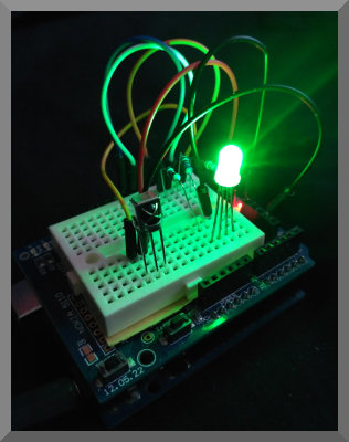
Color Changing LED
Control the color of an RGB LED with an InfraRed Remote.
This example uses the NEC InfraRed protocol for communication.
Pulse Width Modulation (PWM) is used to control
the amount of red, green and blue from the LED.
IR Remote
This example makes use of the IR Remote Creator App, where a remote with 15 buttons has been designed to work with the Arduino code on this page.
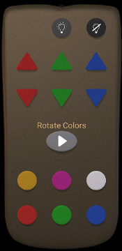
Color Changing LED Remote
The round buttons at the top with lightbulb symbols turn the LED on and off. The triangles buttons increase or decrease the Red, Green or Blue component of the light in set amounts. The oval play button will enter a mode where the light smoothly rotates between colors. The round buttons at the bottom of the remote set the LED to a specific color.
Get the remote for this demo in one of these ways:
1) If you are accessing this page from a device with the app installed, then tap here to load it into the App.
2) Alternatively download led-color.txt into the keuwlsoft/ir-remotes/ directory in the documents folder on your Android device, and then load it from within the app.
3) Alternatively, in the load from web link option within the app, enter: https://www.keuwl.com/ir-remotes/led-color.txt
4) Generate the remote yourself within the App, by creating some buttons and assigning the IR pattern to match those described in the next section.
NEC Protocol
This is a popular InfraRed protocol that has some nice built in error checking. It uses pulse distance modulation on a carrier wave that is typically 38 kHz. The distance between pulses is used to differentiate a 0 or 1.
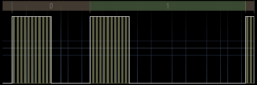
Pulse Distance Modulation
The IR pattern comprises a header pulse, 32 bits of information, and then a stop or end bit. The 32 bits of data are split into an address and a command.
The address decides the target device of the IR transmission whilst the command determines the function on that device.
Both the command and address are sent twice, first as it is, and then as a one's compliment (i.e. inverted) version. For example if the address is 01100111, then the inverted address, address' is 10011000. If the transmitted data hasn't been corrupted, then the logical bitwise AND of the address and address' will yield zero. Likewise for the bitwise AND of command and command'.
As an example of an IR pattern, the pattern for the play (Rotate Colors) button on the remote is shown below.
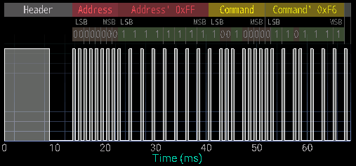
IR pattern for the Rotate Colors Button
For all buttons, the address being used for this demo project is zero. If changing the address of the sent code, make sure the Arduino code is adjusted to match. For example, If you have multiple LED or other IR projects, you can assign them different addresses so that the signal is only received by the one that should receive it.
For the buttons, we have used command numbers 1 to 15 (0x01 to 0x0E hex). Thus the code table for the remote is:
| Button | Address | Command |
| LED Off | 0x00 | 0x01 |
| LED On | 0x00 | 0x02 |
| Red Up | 0x00 | 0x03 |
| Red Down | 0x00 | 0x04 |
| Green Up | 0x00 | 0x05 |
| Green Down | 0x00 | 0x06 |
| Blue Up | 0x00 | 0x07 |
| Blue Down | 0x00 | 0x08 |
| Yellow | 0x00 | 0x09 |
| Pink | 0x00 | 0x0A |
| White | 0x00 | 0x0B |
| Red | 0x00 | 0x0C |
| Green | 0x00 | 0x0D |
| Blue | 0x00 | 0x0E |
There is nothing special about this choice of command numbers. Change them if required and update the Arduino code to match.
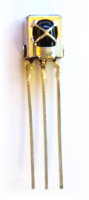
IR Receiver Module
This project used a VS1838B InfraRed Receiver Module. There are a range of IR receiver modules available, the main difference being in the carrier frequency. 38 kHz is by far the most popular frequency for IR remotes, but you will also find 30 kHz, 33 kHz, 36 kHz 40 kHz, 56 kHz and others available. Unless you need a specific frequency to match a particular remote/device, 38 kHz is probably going to be the cheapest and best option. There is some overlap in frequency capability. i.e. expect a 38 kHz receiver to also be able to pick up a 36 kHz signal (for example), but weaker and at a closer range.
Check the datasheet of your IR receiver module so that you connect you device correctly (otherwise it might heat up and burn out and then not work anymore). The IR receivers generally will have three connections: Ground, +V and a Output. Note that the output could be inverted to what you think it is going to be. Checking the data sheet that the IR receiver uses a suitable voltage for your Arduino to supply is probably a good idea too.
The IR receiver packages do all the necessary amplification & demodulation and just output any IR pattern they receive as a digital signal which we will read with the Arduino.
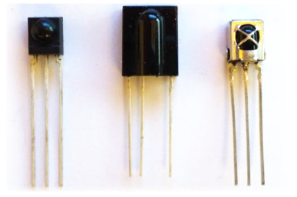
Some IR Receiver Modules (TSOP4838, TSOP31256 and VS1838B).
Pulse Width Modulation
To control the brightness of the RGB LED we use the Pulse Width Modulation (PWM) capability of Pins 9, 10 and 11 on the Arduino Uno. By changing the pulse width, we control the average On time of the pin, such that we can control the power output to a device, such as the LED in this demo. The Arduino analogueWrite() command uses PWM to achieve this. For every 256 counts, the output is held high until the requested analogue write value is reached. This is repeated every 2.04 ms or at 490 Hz (for the 16 MHz Arduino Uno with default settings). Thus a value of 0 will be off all the time, a value of 255 will be on all the time and anything in between will be pulse width modulated to be on for a part of the time.
Components used
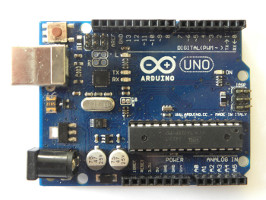
- Arduino Uno
- VS1838B InfraRed Receiver Module
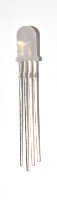
- RGB LED
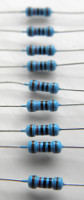
- Resistors for LED
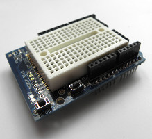
- Prototype Shield for Arduino Uno
Circuit Diagram
The resistors, R, depend on the LED used and can be different for each of the colors of the LED (consult datasheet for your LED). They limit the current so the LED doesn't burn out. The resistances can be trimmed/adjusted to improve color balance.
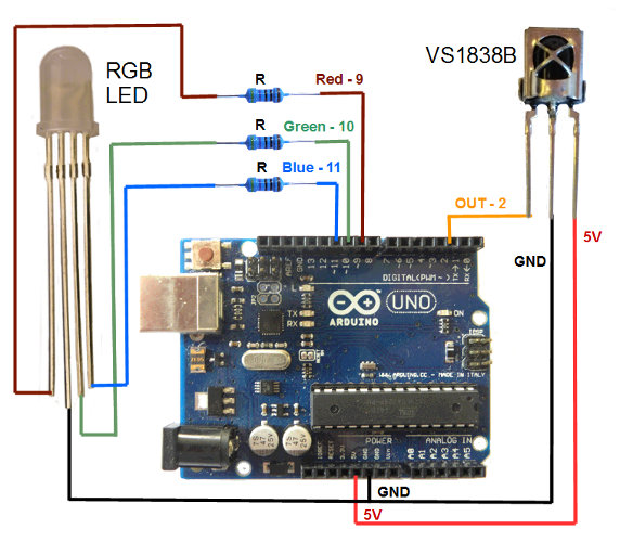
Circuit Diagram for IR Controlled Color Changing LED Project
We are using an Arduino Uno for this demo, although you could use a different model if you prefer, just make sure it has 3 pins with Pulse Width Modulation (PWM) capability and and that the connected pins correspond to that in the Arduino sketch. Also make sure that the IR receiver module's output is connected to one of the external interrupt pins.
Arduino code
Open the Arduino software, select the correct COM Port and Arduino device in the Tools menu, copy and paste the sketch below and click upload.
Of note in this sketch is the way it handles the incomming IR pattern data. Rather than tieing up the main loop with PulseIn() commands and constantly monitoring the IR signal, we have used interrupts instead. This leaves the main loop free to carry out other important tasks.
The interrupt is called every time the external interrupt pin changes state. It logs the elapsed micros() time of the Arduino, and then resumes from where it was before. Once IR pattern data has been collected and a pause is observed at the end of the pattern, it's analysis is done in the main loop.
// IR Controlled Color Changing LED
// By keuwlsoft:  www.keuwl.com  16th Feb 2019
// cc Attribution-ShareAlike
//
// This sketch will receive an IR Pattern, Decode the Address and Command (NEC Protocol) and then apply a change
// to an RGB LED's color based on the command received.
// An Interrupt is used to gather the IR Pattern timing, which is later analysed, thus keeping the main loop free for other tasks.
// Keuwlsofts 'IR Remote Creator' App was used to send the IR signal.
// The Remote can be downloaded at www.keuwl.com/electronics/rduino/ir/01-tricolor-led/


int ir_pin=2; //use pins 2 or 3 for external interupts, connect the IR sensor output here.

long no_change_time=10000; //No change in IR pin for this duration (microseconds) will mark the end of pattern.
const int array_size=100; //Max times to log.  If array is full, it will report the pattern to that point.
long t_array[array_size]; //Array of times of when the IR pin changes state.
int count=0; // Number of times logged to array.
boolean log_micros=true;  //Flag to indicate if able to log times to array
long last_micros=0; //previous array time entry

int addr=0; //Device address decoded from IR pattern
int cmmd=0; //Command decoded from IR pattern
int our_device_addr=0; //integer (0-255) that is an address to identify our device amoungst other devices.

int Red_LED_Pin = 9; // PWM Pin for Red LED
int Green_LED_Pin = 10; // PWM Pin for Green LED
int Blue_LED_Pin = 11; // PWM Pin for Blue LED

//Varibles to hold brightness values ranging from 0 (off) to 255 (fully on)
int Red_value=0;
int Green_value=255;
int Blue_value=0;

boolean new_data=false; //Flag that is set everytime a new IR command is received
boolean LED_on=true; //Flag to indicate if LED is on
boolean Rotate=false; //Flag to indicate if color rotation is on
int Rotate_section=0; //Color rotation is divided into 6 sections.
int Rotate_step=4; //How much to change color each update.  Decrease for slower color rotation.


void setup() {

  pinMode(ir_pin, INPUT);

  //attach an interupt to log when the IR pin changes state
  attachInterrupt(digitalPinToInterrupt(ir_pin),interupt,CHANGE);

  // Initialise LED pins as outputs
  pinMode(Red_LED_Pin, OUTPUT);
  pinMode(Green_LED_Pin, OUTPUT);
  pinMode(Blue_LED_Pin, OUTPUT);

}

void loop() {

//=========================================== Extract IR Command
  if (count>0){
    if (!log_micros|((micros()-last_micros)>no_change_time)){
      log_micros=false; //make sure array not modified while we analyse it
      //Get Pattern
      count--;
      for (int i=0;i<count;i++){
        t_array[i]=t_array[i+1]-t_array[i];
      }
      //Extract Command And Address of NEC protocol
      if (count>=64){ //Check patten long enough for 32 bits of data
        int pos=count;
        // Extract Command Compliment
        int cmmd2=0x00;
        for (int i=0;i<8;i++){
          cmmd2=cmmd2<<1; pos-=2;
           if (t_array[pos]>1000)cmmd2=cmmd2|1;
        }
        // Extract Command
        cmmd=0x00;
        for (int i=0;i<8;i++){
          cmmd=cmmd<<1; pos-=2;
          if (t_array[pos]>1000)cmmd=cmmd|1;
        }
        //Extract Address Complement
        int addr2=0x00;
        for (int i=0;i<8;i++){
          addr2=addr2<<1; pos-=2;
          if (t_array[pos]>1000)addr2=addr2|1;
        }
        //Extract Address
        addr=0x00;
        for (int i=0;i<8;i++){
          addr=addr<<1; pos-=2;
          if (t_array[pos]>1000)addr=addr|1;
        }

        //check if data was for our device and is valid
        if ((addr2&addr)==0&&(addr2&addr)==0){
          if (addr==our_device_addr) new_data=true;
        }
      }

    log_micros=true; count=0; //Reset array so another IR pattern can be received
    }
  }
//===========================================


//=========== Do Something with the Newly Received Command
  if (new_data){
    if (cmmd==1) LED_on=false; //Turn LED Off
    if (cmmd==2) LED_on=true; //Turn LED On
    if (cmmd==3){ // Increase Red Component
      Red_value+=16; Rotate=false;
      if (Red_value>255) Red_value=255;
    }
    if (cmmd==4){ // Decrease Red Component
      Red_value-=16; Rotate=false;
      if (Red_value<0) Red_value=0;
    }
    if (cmmd==5){ // Increase Green Component
      Green_value+=16; Rotate=false;
      if (Green_value>255) Green_value=255;
    }
    if (cmmd==6){ // Decrease Green Component
      Green_value-=16; Rotate=false;
      if (Green_value<0) Green_value=0;
    }
    if (cmmd==7){ // Increase Blue Component
      Blue_value+=16; Rotate=false;
      if (Blue_value>255) Blue_value=255;
    }
    if (cmmd==8){ // Decrease Blue Component
      Blue_value-=16; Rotate=false;
      if (Blue_value<0) Blue_value=0;
    }
    if (cmmd==9) Rotate=!Rotate; //Play (Rotate Colors)
    if (cmmd==10){ //Orange
      Red_value=180; Green_value=135; Blue_value=0; Rotate=false;
    }
     if (cmmd==11){ //Pink
      Red_value=200; Green_value=70; Blue_value=100; Rotate=false;
    }
    if (cmmd==12){ //White
      Red_value=255; Green_value=255; Blue_value=255; Rotate=false;
    }
    if (cmmd==13){ //Red
       Red_value=255; Green_value=0; Blue_value=0; Rotate=false;
    }
    if (cmmd==14){ //Green
       Red_value=0; Green_value=255; Blue_value=0; Rotate=false;
    }
    if (cmmd==15){ //Blue
       Red_value=0; Green_value=0; Blue_value=255; Rotate=false;
    }
    new_data=false;
  }
//===========


//=========== Rotating Color Effect
  if (Rotate){
    if (Rotate_section==0){ //Increase Green
      Green_value+=Rotate_step;
      if (Green_value>=255){
        Green_value=255; Rotate_section++;
      }
    }else if (Rotate_section==1){ //Decrease Red;
      Red_value-=Rotate_step;
      if (Red_value<=0){
        Red_value=0; Rotate_section++;
      }
    }else if (Rotate_section==2){ //Increase Blue
      Blue_value+=Rotate_step;
      if (Blue_value>=255){
        Blue_value=255; Rotate_section++;
      }
    }else if (Rotate_section==3){ //Decrease Green
      Green_value-=Rotate_step;
      if (Green_value<=0){
        Green_value=0; Rotate_section++;
      }
    }else if (Rotate_section==4){ //Increase Red
       Red_value+=Rotate_step;
       if (Red_value>=255){
         Red_value=255; Rotate_section=0;
       }
    }else if (Rotate_section==5){ //Decrease Blue
       Blue_value-=Rotate_step;
       if (Blue_value<=0){
         Blue_value=0; Rotate_section++;
       }
    }
  }
//===========


//=========== Update LED Brightness
  if (LED_on){
    analogWrite(Red_LED_Pin, Red_value);
    analogWrite(Green_LED_Pin, Green_value);
    analogWrite(Blue_LED_Pin, Blue_value);
  }else{
    analogWrite(Red_LED_Pin, 0);
    analogWrite(Green_LED_Pin, 0);
    analogWrite(Blue_LED_Pin, 0);
  }
//===========

  delay(10);
}


//========================================================
// Interupt to log each time the IR signal changes state
void interupt(){
  if (log_micros){
    long m=micros();
    if (count>0&&(m-last_micros)>no_change_time){
      log_micros=false;
    }else{
       t_array[count]=m;
       count++;
       last_micros=m;
       if (count>=array_size) log_micros=false;
     }
  }
}
//========================================================
Rotating Color Effect
To create a smooth rotating color, we have divided the color loop into 6 sections, where one of the color components is increased or decreased in each section. The color starts at red, and moves around the color wheel.
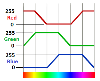
Color Rotation
This is a simple and effective way to rotate colors. However it omits white in the the rotation, any subtle tones, and timing does not consider the space each human perceived color takes up in the color wheel, such that some colors will seem to persist for longer than others.
Why not have a go at modifying the code to include white or perhaps to move between random colors.