LED Ring Demo
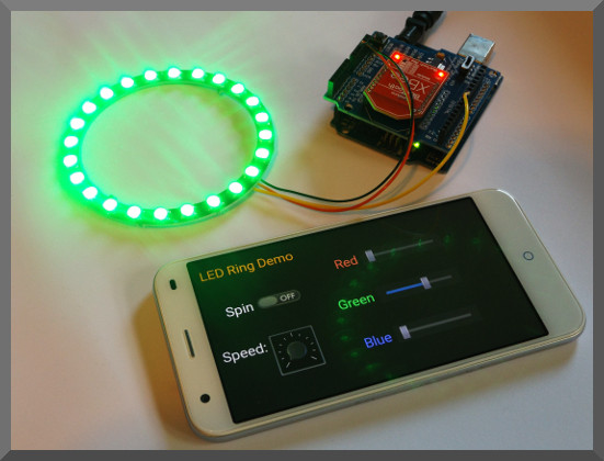
A NeoPixel Ring is controlled using an Arduino Uno linked with an XBee Bluetooth module and shield to an Android device running the Bluetooth Electronics app.
About this demo
The NeoPixel Ring comprises a chain of WS2812 components. Each WS2812 combines an RGB LED with an Integrated Circuit (IC) to drive the LED. The LED is also known as 5050 and is 5 mm by 5 mm in size. Each WS2812 has 4 connections, GND, +V, Data In and Data Out. If used in a chain, the Data Output of one WS2812 feeds into the Data In of the next WS2812. The Voltage supplied to the NeoPixel Ring was 5 V. The number of LEDs in the ring can vary, but for this demo a 12 pixel and a 24 pixel ring were trialled. These WS2812 packages also come as a strip on a reel. Each Ring has 4 connections, GND, +5, Data in for the first LED and Data Out from the last LED in the chain. The data out line can be connected to the data in of another NeoPixel ring or WS2812 strip if desired lengthening the number of LEDs in the chain. The more LEDs used, the slower the update rate will be and probably also the more susceptible to timing accuracy.
CAUTION – These LEDs can be bright, avoid staring into them. Also flashing lights on and off rapidly can cause epileptic fits in some people.
In the Bluetooth electronics app and the panel loaded, Red, Green and Blue Sliders can be used to control the colour of the LEDs. Either all the LEDs are lit, or one LED can be set to move around the ring by turning the 'spin' switch to on.
WS2812 timing
The Data In receives the 24-Bit RGB value of the LEDs in turn starting with the first LED in the cascade. None of the LEDs are updated until a long low is received of approx 50 microseconds or longer. Strangely, this IC likes to receive the green data bits first, thus the data is sent GRB rather than RGB. The most significant bit is sent first, thus if we are sending a decimal 128 value, (0x80 in hex) we would send '10000000'. If the whole RGB value was '#80FF37' we would send '111111111000000000110111'. for each bit, we send a pulse over the data line. Several data sheets contain slightly different information regarding the timings so the following is my understanding of how these work. For a '0' we hold the data line High for approx 350 ns. For a '1', we hold the data line high for twice as long (approx 700 ns). We then hold the data line low such that the high and low time for a bit totals approximately 1250 ns. In practice (at least for a small NeoPixel ring), the on (high) times seems to be the more critical, and pausing the data line low for much longer times with between the 24 Bit LED patterns doesn't seem to pose a problem unless the pause gets close to the 50 mircosecond trigger which will reset all the LEDs output.
Lets look at that timing a little closer. 350 ns high time. With a 16 MHz clock speed, we have a clock cycle time of 62.5 ns. Therefore we need to hold the data line High for 5.6 clock cycles. In Arduino we have the delayMicroseconds() function, but this only accepts integers and is only accurate down to 3 microseconds (3000 nanoseconds). Therefore controlling the timing with the standard Arduino commands isn't going to work. Coding in assembly is the best solution to control the timing this accurately. Since this is more complicated to achieve, the easiest solution is to use one of several drivers that have been written for the WS2812 Neopixel ring or strips . The other solution is to write the assembly code ourselves. Since we know you like to learn stuff, we have chosen to write it ourselves, so you if not already familiar with assembly code, you can start to appreciate how assembly code can be implemented within your Arduino code and perhaps even start modifying it or writing your own assembly code. Assembly code can control timing much more accurately since each command takes a known number of clock cycles, such that the high time for a '0' can be made to take 6 clock cycles exactly, which is close enough to the 350 ns high time required.
Since each '1' or '0' take approximately 1.25 microseconds, we need 35 microseconds for each LED in the chain. Thus for a 24 LED Ring we require 840 microseconds to update all the data, and an extra 50 microseconds or more to send the Reset signal. Thus our maximum update speed with 24 LEDs is approximately 1.1 kHz.
Components used
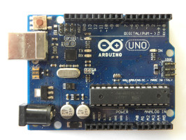
- Arduino Uno
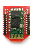
- XBee Bluetooth Module
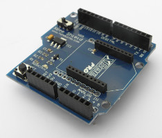
- XBee Shield
- NeoPixel Ring
Circuit Diagram
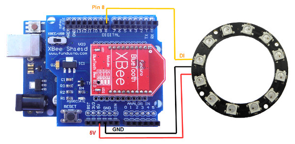
Whilst we are using an Arduino Uno for this demo, any Arduino with an ATmega328P processor operating at 16 MHz should work. This is because the assembly code was written for this processor based on a clock cycle of 62.5 nanoseconds. If, for example the processor was run at 8 MHz, the clock cycle will be 125 nanoseconds and the '1' and '0' data pulses will take twice as long and be misinterpreted by the WS2812 package. Whilst other processors might have have a different resister map (e.g. Port B might not map to the same 0x05 location used for the Atmega328P). The Arduino Nano and Arduino Mini both have Atmega328P 16 MHz options. For other arrangements, the code might need modification.
Only 3 connections are required between the Arduino and NeoPixel Ring, GND, 5V and a data in. The Data In is connected to Pin 8 on the Arduino (which is Port B, bit 0).
As for the Bluetooth part of the circuit, just plug the Bluetooth module into the shield and the shield into the Arduino. Note that there is a switch on the Bluetooth shield. Connect this to USB for programming, and the back to XBee when connecting via Bluetooth.
Arduino code
// WS2812 LED Ring Demo
// By keuwlsoft:  www.keuwl.com  15th Apr 2016
// cc Attribution-ShareAlike

// The WS2812 components are chained together and run of just one data line.
// The data line needs control of the high/low times to be less than a microsecond.
// Therefore assembly code is used to update the LEDs in function colorRing();
// This code assumes an Arduino Uno, or equavalent board with ATmega328P with a 16 MHz Clock speed.

int red = 50; // Red part of LED colour 0 to 256
int green = 10; // Green part of LED colour 0 to 256
int blue = 0; // Blue part of LED colour 0 to 256
int no_of_leds = 24; //set this to the number of LEDs on your Ring
int mode = 0; //0 = all leds lit, 1 = spin
int led_pos = 1; //position of led to be lit (used in spin mode)

char BluetoothData; // the data received from bluetooth serial link
int interval=40; //in milliseconds.  Determines speed of updates & spin effect,
unsigned long lastUpdateTime=0;

void setup() {
    pinMode(8, OUTPUT); //Pin 8 used for led data line
    digitalWrite(8,LOW);

  //Initiate Serial for Bluetooth Communication
    Serial.begin(9600);
}

void loop() {

  //Process any info coming from the bluetooth serial link
  if (Serial.available()){
    BluetoothData=Serial.read(); //Get next character from bluetooth
    if(BluetoothData=='R') red=Serial.parseInt(); //Read Red value
    if(BluetoothData=='G') green=Serial.parseInt(); //Read Green Value
    if(BluetoothData=='B') blue=Serial.parseInt(); //Read Blue Value
    if(BluetoothData=='A') mode=1; //Spin Mode
    if(BluetoothData=='a') mode=0; //All Leds On Mode
    if(BluetoothData=='S') interval=150-Serial.parseInt(); //Read Interval
    if(BluetoothData=='N') no_of_leds=Serial.parseInt(); //Read Number of LEDs
  }

  //See if its time to update the LEDs
  unsigned long t=millis();
  if ((t-lastUpdateTime)>interval){
    colorRing(); //update the LED colors
    lastUpdateTime=millis();
    led_pos++; //point to next led for spin effect
    if (led_pos>no_of_leds) led_pos=1; //go back to the first led when the end is reached
  }

}


void colorRing(){
  // Assembly code to update LED colors
  // Loops though all LEDs in order
  // For each LED,  8 Green bits are sent first, followed by the 8 red bits and finally the 8 blue bits
  // The Most Signifiacnt Bit (MSB) is sent first

  cli(); //dissable interupts whilst we update LEDs

  asm("mov R17,%0 \n\t":  "+r" (no_of_leds)); //Store number of leds in Register 17
  asm("mov R22,%0 \n\t":  "+r" (led_pos));    //Store LED lit position in Register 22
  asm("mov R21,%0 \n\t":  "+r" (mode));       //Store mode in Register 21

  asm("LedLoop:\n\t"); //Start of Loop for each LED

  //Set color for LED
    asm("cpi R21,0x00 \n\t"); //See if we are in 'all on' mode
    asm("breq on\n\t");       //if so, all LEDs are lit -> jump to LED on code
    asm("cp R22,R17 \n\t");   //else we see if this LED is the one to be lit
    asm("brne off\n\t");      //if not, we jump to the LED off code.
    asm("on: \n\t"); // LED on
      asm("mov R18,%0 \n\t":  "+r" (red));   //Store Red part of Color in Register 18
      asm("mov R19,%0 \n\t":  "+r" (green)); //Store Green part of Color in Register 19
      asm("mov R20,%0 \n\t":  "+r" (blue));  //Store Blue part of Color in Register 20
      asm("jmp cont \n\t");
    asm("off: \n\t"); // LED off
      asm("ldi R18,0x00 \n\t"); // Red = 0
      asm("ldi R19,0x00 \n\t"); // Green = 0
      asm("ldi R20,0x00 \n\t"); // Blue = 0
   asm("cont: \n\t");


  ///// GREEN - Send green bits out to Pin 8
    asm("ldi R16,0x08 \n\t"); // Number of green bits (8) to send put in Register R16
    asm("GreenLoop: \n\t");   // Start of Loop for green bits
      asm("sbrs R19,7 \n\t");    //Test bit 7 of the green byte, Skip next command if a 1
      asm("jmp GreenZero \n\t"); //jump over the write 'one' code

      //write a 'one' to the Leds data line
      asm("sbi 5,0 \n\t");  //Set Port B Bit 0 (aka Output Pin 8) to High
      asm("nop\n\t""nop\n\t""nop\n\t""nop\n\t""nop\n\t""nop\n\t""nop\n\t""nop\n\t""nop\n\t""nop\n\t");
      asm("cbi 5,0 \n\t"); //Set Port B Bit 0 to Low
      asm("nop\n\t""nop\n\t""nop\n\t""nop\n\t""nop\n\t"); //Wait a few clock cycles
      asm("jmp GreenCont \n\t");  //jump over the write 'zero' code

      //write a 'zero' to the Leds data line
      asm("GreenZero:\n\t");
      asm("sbi 5,0\n\t"); //Set Port B Bit 0 (aka Output Pin 8) to High
      asm("nop\n\t""nop\n\t""nop\n\t""nop\n\t""nop\n\t"); //Wait a few clock cycles
      asm("cbi 5,0\n\t"); //Set Port B Bit 0 to Low
      asm("nop\n\t""nop\n\t""nop\n\t""nop\n\t""nop\n\t""nop\n\t""nop\n\t""nop\n\t");

      asm("GreenCont:\n\t");
      asm("lsl R19\n\t"); //Rotate the green Byte so that we point to next bit
      asm("dec R16\n\t"); //Decrease the count of green bits left to do
      asm("cpi R16,0x00\n\t"); //See if we have counted down to zero
      asm("brne GreenLoop\n\t"); //If not zero, Loop back and do the next green bit


  ///// RED - Send red bits out to Pin 8
    asm("ldi R16,0x08 \n\t"); // Number of red bits (8) to send put in Register R16
    asm("RedLoop: \n\t"); // Start of Loop for Red bits
      asm("sbrs R18,7 \n\t"); //Test bit 7 of the Red byte, Skip next command if a 1
      asm("jmp RedZero \n\t"); //jump over the write 'one' code

      //write a 'one' to the Leds data line
      asm("sbi 5,0 \n\t");  //Set Port B Bit 0 (aka Output Pin 8) to High
      asm("nop\n\t""nop\n\t""nop\n\t""nop\n\t""nop\n\t""nop\n\t""nop\n\t""nop\n\t""nop\n\t""nop\n\t");
      asm("cbi 5,0 \n\t"); //Set Port B Bit 0 to Low
      asm("nop\n\t""nop\n\t""nop\n\t""nop\n\t""nop\n\t");
      asm("jmp RedCont \n\t");  //jump over the write 'zero' code

      //write a 'zero' to the Leds data line
      asm("RedZero:\n\t");
      asm("sbi 5,0\n\t"); //Set Port B Bit 0 (aka Output Pin 8) to High
      asm("nop\n\t""nop\n\t""nop\n\t""nop\n\t""nop\n\t");
      asm("cbi 5,0\n\t"); //Set Port B Bit 0 to Low
      asm("nop\n\t""nop\n\t""nop\n\t""nop\n\t""nop\n\t""nop\n\t""nop\n\t""nop\n\t");

      asm("RedCont:\n\t");
      asm("lsl R18\n\t"); //Rotate the Red Byte so that we point to next bit
      asm("dec R16\n\t"); //Decrease the count of red bits left to do
      asm("cpi R16,0x00\n\t"); //See if we have counted down to zero
      asm("brne RedLoop\n\t"); //If not zero, Loop back and do the next Red bit


  ///// BLUE - Send blue bits out to Pin 8
    asm("ldi R16,0x08 \n\t"); // Number of Blue bits (8) to send put in Register R16
    asm("BlueLoop: \n\t"); // Start of Loop for Blue bits
      asm("sbrs R20,7 \n\t"); //Test bit 7 of the Blue byte, Skip next command if a 1
      asm("jmp BlueZero \n\t"); //jump over the write 'one' code

      //write a 'one' to the Leds data line
      asm("sbi 5,0 \n\t");  //Set Port B Bit 0 (aka Output Pin 8) to High
      asm("nop\n\t""nop\n\t""nop\n\t""nop\n\t""nop\n\t""nop\n\t""nop\n\t""nop\n\t""nop\n\t""nop\n\t");
      asm("cbi 5,0 \n\t"); //Set Port B Bit 0 to Low
      asm("nop\n\t""nop\n\t""nop\n\t""nop\n\t""nop\n\t");
      asm("jmp BlueCont \n\t");  //jump over the write 'zero' code

      //write a 'zero' to the Leds data line
      asm("BlueZero:\n\t");
      asm("sbi 5,0\n\t"); //Set Port B Bit 0 (aka Output Pin 8) to High
      asm("nop\n\t""nop\n\t""nop\n\t""nop\n\t""nop\n\t");
      asm("cbi 5,0\n\t"); //Set Port B Bit 0 to Low
      asm("nop\n\t""nop\n\t""nop\n\t""nop\n\t""nop\n\t""nop\n\t""nop\n\t""nop\n\t");

      asm("BlueCont:\n\t");
      asm("lsl R20\n\t"); //Rotate the Blue Byte so that we point to next bit
      asm("dec R16\n\t"); //Decrease the count of blue bits left to do
      asm("cpi R16,0x00\n\t"); //See if we have counted down to zero
      asm("brne BlueLoop\n\t"); //If not zero, Loop back and do the next Blue bit

  // See if we have more LEDs to update
    asm("dec R17\n\t");      //Decrease the count of LEDs left to update
    asm("cpi R17,0x00\n\t"); //See if we have counted down to zero
    asm("breq Done\n\t");    //If zero, jump to Done
    asm("jmp LedLoop\n\t");  //Else, send the data for the next LED in the chain
    asm("Done:\n\t");        //Done, awesome!

    sei(); //enable interupts again
}
Programming the Arduino
To program the device, make sure you remove pins 0 and 1 to the Bluetooth module otherwise the Arduino will get confused trying to communicate to two serial devices simultaneously on the same pins. On the XBee shield there is a switch to select whether the 0 and 1 pins are connected to the USB or XBee Bluetooth module. Make sure to switch back after programming. Run the Arduino software, select the correct COM Port and Arduino device in the Tools menu. Copy and paste the above sketch and click upload.
Funtion colorRing(); updates all the LED colours. The number of LEDs in the ring must be specified in the no_of_leds integer, since this value is used in the main loop of the colorRing(); function to count how many times a 24bit GRB data set should be sent. This value is first taken into Register R17, and then decremented each loop until it reaches zero.
At the start of the assembly and at the end the interrupts are disabled and enabled respectively just to make sure the processor doesn't decide to go off and do anything else whilst sending this data out and mess up the timings.
Assembly commands are wrapped in the asm(“ "); structure. The above code is commented to describe roughly what is going on line by line. The R18, R19, R20 etc. are registers which can be used to hold 8-bit integers as variables for assembly coding. They are used in the code to hold the Red, Green and Blue values and also for counting loops. The labels ending with a ':' mark points which the code will branch or jump to. The abbreviations of the assembly commands used are listed below:
NOP – No Operation
DEC– Decrement
LSL – Logical Shift Left
LDI – Load Immediate
MOV – Move
SBI – Set Bit in I/O
CBI – Clear Bit in I/O
CP – Compare
CPI – Compare with Immediate
JMP – Jump
BREQ – Branch if Equal
BRNE – Branch if Not Equal
SBRS – Skip if Bit in Register Set
For a more detailed explanation of the commands, their operands, the number of clock cycles they take, and all the other assembly commands available, take a look at the instruction set manual for the processor being used.
Bluetooth Electronics App
1) Run the Bluetooth Electronics app, click edit.
2) Select library and navigate to the 'LED Ring' demo and copy to panel.
3) Now connect to the Bluetooth device. Turn on power to your circuit so that the LED on the Bluetooth module starts flashing. Click connect on the main screen of the app. If not already paired, click on discover and wait for the device to appear in the list below. Select the device (e.g. HC-06) and click on pair. When requested you will need to enter a pin number, which is usually 1234 for these devices. Once paired, the device will appear on the right hand side. Select it and click on connect. Hopefully this was successful, return to the main screen.
4) The run button should be enabled now that we have connected to the Bluetooth device. Click run and test it out.