Stepper Motor Control Demo
Control two stepper motors with your Android device. on an HC-06 Bluetooth module.
About this demo
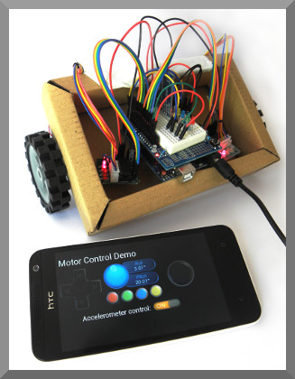
Two 28BYJ-48 Stepper motors are driven from ULN2003 units controlled from an Arduino Uno. An HC-06 Bluetooth module is included so that the motors can be controlled from an Android device running Keuwlsoft's Bluetooth Electronics app.
To make this demo a little more exciting, the two stepper motors have been connected to wheels, so that we are controlling a small car. Note that speeds are slow, very slow, so use large wheels. Stepper motors are great if accuracy in position is required. If speed is required, an ordinary motor will be better.
This example demonstrates the accelerometer and pad controls in the 'Bluetooth Electronics' app, showing how they can be interfaced to your electronic circuits via Bluetooth. If the accelerometer control switch is on, then tilting the Android device will control the car motion. If switched off, then either of the two pad controls will make the car move. The pad on the left will allow operate car motion at maximum speed, whereas the pad on the right will allow the car to move at varying speeds. The 4 buttons are control 4 LEDs on the car, although these could be omitted or swapped for some other effect if preferred.
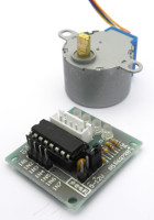
28BYJ-48 Stepper Motors and the ULN2003 Driver
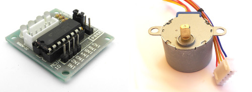
28BYJ-48 Stepper Motor and ULN2003 Driver
These are small cheap unipolar motors. The can operate up to approx 15RPM and have a decent torque. In full (8 step) mode, there are 4096 (approx) steps per revolution, although we are using the Arduino 'stepper.h' library and operating it in 4 step mode. Thus there are 2048 steps per revolution. The motor is internally geared at a ratio of 64. Each step will turn the internal rotor 5.625° (or 11.25° in 4 step mode). There are 5 connections, Red being the common, and the other four colours connected to the ends of the solenoids in the motor, with Blue (A), Pink (B), Yellow (C) and Orange (D) connected to the UNL2003 driver circuits which has corresponding LEDs labelled A to D.
The UNL2003 is used so that sufficient current can be drawn to drive the motor and protect the digital circuit from any back emfs. The UNL2003 consists of an array of 8 Darlington transistor pairs suitable for switching inductive loads. These often come on a circuit board with connector socket for the motor and LEDs to indicate the switching state making it easier for debugging and prototyping.
Components used
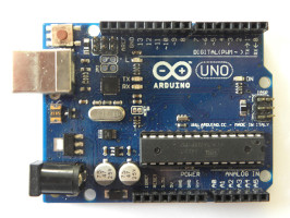
- Arduino Uno
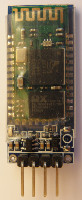
- HC-06 Bluetooth Module
- 28BYJ-48 Stepper Motor and ULN2003 Driver
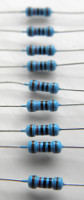
- 10k and 20k Resistors
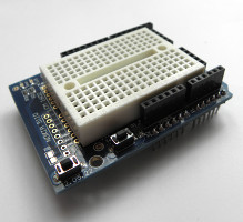
- Prototype Shield for Arduino Uno
Circuit Diagram
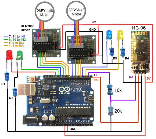
The Bluetooth modules have 4 connections, GND, 5V, RX and TX. The TX pin on the Bluetooth module connects to the RX pin on the Arduino and visa versa. For serial communication, a transmit (TX) connection needs to be received by a (RX) connection.
Note that the Bluetooth module operates at 3.3V. Supplying a 5V to the Bluetooth RX pin could damage it, such that a voltage divider should be used to supply a 3.3V signal to the RX pin. This is achieved in this demo with a 20k and 10k resistor. The TX pin of the Bluetooth module does not need modification and can connect directly to the Arduino RX pin. This is because the HIGH on 3.3V logic will still be recognised as a HIGH on the 5V logic circuitry on the Arduino.
Arduino code
// Motor Control Via Bluetooth Demo
// By keuwlsoft:  www.keuwl.com  4th Oct 2015
// cc Attribution-ShareAlike

// This sketch controls two 28BYJ-48 stepper motors using an Arduino Uno
// and ULN2003 Drivers.  Control is achieved by Bluetooth using an HC-06
// module and an Android device with keuwlsofts 'Bluetooth Electronics' App.
// Sketch assumes that it is controlling motors attached to two wheels of a car.

#include <Stepper.h>

int steps_per_rev = 2048;
Stepper stepper2(steps_per_rev, 4,6,5,7); //Left Stepper
Stepper stepper1(steps_per_rev, 8,10,9,11); //Right Stepper

int steps1=0; //number of steps for Left Stepper each loop
int steps2=0;
int roll,pitch; //roll and pitch sent from Android device
int pad_x,pad_y; //control pad values sent from Andorid device
char BluetoothData; // the Bluetooth data received
boolean acc_on=false; //Flag to inidicate if to use accelerometer values

void setup() {

  stepper1.setSpeed(10); //Set Stepper speed in RPM
  stepper2.setSpeed(10);

  //Set Digital Pins 2, 3, 12 and 13 as Output
  pinMode(2,OUTPUT);
  pinMode(3,OUTPUT);
  pinMode(12,OUTPUT);
  pinMode(13,OUTPUT);

  Serial.begin(9600); //Initialise commuication for Bluetooth
}

void loop() {

  //Check Bluetooth for new Instructions
  if (Serial.available()){
    BluetoothData=Serial.read(); //Get next character from bluetooth

   //**** Accelerometer  -  sends 'Aroll,pitch*' every 150 ms
     if(BluetoothData=='A'){
      roll=Serial.parseInt();
      while (BluetoothData!='*'){
        if (Serial.available()){
          BluetoothData=Serial.read(); //Get next character from bluetooth
          if(BluetoothData==',')pitch=Serial.parseInt();
        }
      }
      if (acc_on){
       //Algorithm to convert roll and pitch into step movements for each loop
        if (roll>50) roll=50;
        if (roll<-50) roll=-50;
        if (pitch<45) pitch=45;
        if (pitch>135) pitch=135;
        steps1=steps2=(90.0-pitch)/4.5;
        if (roll>0) steps2-=steps1*roll/25.0;
        if (roll<0) steps1+=steps2*roll/25.0;
      }
    }
    if(BluetoothData=='B')acc_on=true;
    if(BluetoothData=='b'){
      acc_on=false;
      steps1=steps2=0;
    }

  //**** LEDs
    if(BluetoothData=='P') digitalWrite(2,HIGH);
    if(BluetoothData=='p') digitalWrite(2,LOW);
    if(BluetoothData=='Q') digitalWrite(3,HIGH);
    if(BluetoothData=='q') digitalWrite(3,LOW);
    if(BluetoothData=='R') digitalWrite(12,HIGH);
    if(BluetoothData=='r') digitalWrite(12,LOW);
    if(BluetoothData=='S') digitalWrite(13,HIGH);
    if(BluetoothData=='s') digitalWrite(13,LOW);

  //**** Control Pad on Right -  Sends 'X__,Y___*' every 150ms
    if(BluetoothData=='X'){
      pad_x=Serial.parseInt();
      while (BluetoothData!='*'){
        if (Serial.available()){
          BluetoothData=Serial.read(); //Get next character from bluetooth
          if(BluetoothData=='Y')pad_y=-Serial.parseInt();
        }
      }
      //Algorithm to convert pad position to number of steps for each motor
      float mag=sqrt(pad_y*pad_y+pad_x*pad_x);
      if (mag>10) mag=10;
      if (pad_y<0) mag=0-mag;
      steps1=steps2=mag;
       if (pad_x>0){ //turning right
        steps2=steps2-mag*pad_x/5.0;
      }else{ //turnign left
        steps1=steps1+mag*pad_x/5.0;
      }
    }

  //**** Control Pad on Left
    if(BluetoothData=='0') steps1=steps2=0; //Release
    if(BluetoothData=='1') steps1=steps2=10; //Up
    if(BluetoothData=='3') steps1=steps2=-10; //Down
    if(BluetoothData=='4') { //Left
      steps1=-10;
      steps2=10;
    }
    if(BluetoothData=='2') { //Right
      steps1=10;
      steps2=-10;
    }

  }

//**** Move Stepper Motors (Lasts ~60ms, if not, delay added to make it ~60ms)
  unsigned long t=millis();
  stepper1.step(steps1);
  stepper2.step(-steps2); //stepper 2 is positioned opposite orientation to stepper 1
  t=millis()-t; //calc time since started stepping
  if (t<60)delay(60-t); //add any extra time to make it up to 60ms

}
Programming
To program the device, make sure you remove pins 0 and 1 to the Bluetooth module otherwise the Arduino will get confused trying to communicate to two serial devices simultaneously on the same pins. Re-connect them after programming. Select the correct COM Port and Arduino device in the Tools menu. Copy and paste the above sketch and click upload.
Note that the steppers are operated in turn, thus limiting the speed of the motors. This also makes the movement a bit jumpy. This is because the stepper step function is blocking and waits to complete before proceeding with the next command. For optimal speed and control, you will need to find another suitable library or write your own step function to turn the digital pins of both steppers on and off in the correct sequence.
Bluetooth Electronics App
1) Run the Bluetooth Electronics app, click edit.
2) Select library and navigate to the 'Motor Control Demo' and copy to panel.
3) Now connect to the Bluetooth device. Turn on power to your circuit so that the LED on the Bluetooth module starts flashing. Click connect on the main screen of the app. If not already paired, click on discover and wait for the device to appear in the list below. Select the device (e.g. HC-06) and click on pair. When requested you will need to enter a pin number, which is usually 1234 for these devices. Once paired, the device will appear on the right hand side. Select it and click on connect. Hopefully this was successful, return to the main screen.
4) The run button should be enabled now that we have connected to the Bluetooth device. Click run and test it out.