
Persistence of Vision LED Demo
Create cool effects from just 8 LEDs turned on and off rapidly as they are moved relative to viewer.
About this demo
This demo uses persistence of vision to enable a line of 8 LEDS to display text when they are moved. An Arduino nano and 8 LEDs were used to achieve the effect. A Bluetooth HC-05 or HC-06 module was used to communicate to an Android device with Bluetooth. The Bluetooth Electronics app was then used to control the speed of the effect or update the displayed text.
WARNING: Contains flashing lights. Flashing lights can cause epileptic fits in some people, so use with caution.

Persistence of Vision Demo Build
Each character is represented on an 8x8 grid. 64 bits of information are needed to describe this 8 by 8 pattern. For the software, this was split into two unsigned long 32-bit variables to describe the left and right halves of the character separately. The arrangement of bits in the 8x8 pattern are top to bottom then left to right as illustrated below:

Bit arrangement and letter 'Z 'pattern on 8x8 grid.
For the above example (the letter 'Z'), starting from top left, bit 1 is 1, bit 2 is 0 and so on. Note that bit 1 is the least significant bit (the one on the right of the binary number). Thus we have 01001001010100010110000101000001 binary (1230070081 decimal) for the left half of the character and 00000000010000010100001101000101 binary (4277061 decimal) for the right half of the character. These pairs of numbers are stored sequentially in the data_table[] array to represent ASCII characters from 32 (space character) up to 125 ( } character).
Components used
- Arduino nano
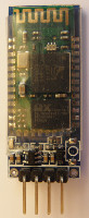
- HC-06 Bluetooth Module
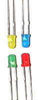
- 8 LEDs
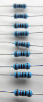
- 470 Ω (depends on LED), 10k and 20k
- and some Cables


Circuit Diagram

The LEDs have a current limiting resistor in series. In this circuit 470 Ω resistors were used. The resistance, R, will depend on the LEDs used, but selected so that the LEDs don't draw too much current and burn out.
We are using an Arduino Nano for this demo, although you could use a different model if you prefer. For this demo we use pins 5 through to 12 as outputs to control the LEDs.
The Bluetooth module has 4 connections, GND, 5V, RX and TX. The TX pin on the Bluetooth module connects to the RX pin on the Arduino and visa versa. For serial communication, a transmit (TX) connection need to be received by a (RX) connection.
Note that the Bluetooth module operates at 3.3V. Supplying a 5V to the Bluetooth RX pin could damage it, such that a voltage divider should be used to supply a 3.3V signal to the RX pin. This is achieved in this demo with a 20k and 10k resistor. The TX pin of the Bluetooth module does not need modification and can connect directly to the Arduino RX pin. This is because the HIGH on 3.3V logic will still be recognised as a HIGH on the 5V logic circuitry on the Arduino.
Arduino code
// Persistance of vision LEDs with Bluetooth Link Demo
// By keuwlsoft:  www.keuwl.com  31st Aug 2015
// cc Attribution-ShareAlike
//
// This sketch controls 8 LEDs on Pins 5 to 12 such that they display
// text when they are moved. The string can be changed by sending a string
// terminated with <CR> via the serial link.  Accepted ASCII characters:
// " !"#$%&'()*+,-./0123456789:;<=>?@ABCDEFGHIJKLMNOPQRSTUVWXYZ[\]^_'abcdefghijklmnopqrstuvwxyz{|}"


String str="keuwl persistence of vision demo"; //string to display via persistance of vision
int pos=0; //current position in str
unsigned long data; // data describing first half of current character
unsigned long data2; // data describing second half of current character
char BluetoothData; // the data received from bluetooth serial link
int interval=5;// interval between columns in ms - determine speed of effect

//Conversion table (each value represents half of a 8x8 grid character)
unsigned long data_table[]={0,0,3755933696,0,459520,198400,337605648,268156,1241467174,50,135406914,2183716,1497709056,21025,197632,0, // !"#$%&'
  1094582272,0,1044447232,0,2132025856,8724,1040713728,2056,1621098496,0,134742016,2056,1616904192,0,204521472,3, //()*+,-./
  1094795582,62,1082081792,0,1230070082,70,1229537570,54,2131891224,16,1229539599,49,1229539646,48,225509633,3, //01234567
  1229539638,54,1229539590,62,909508608,0,1991639040,0,571738112,65,336860160,5140,337789184,8,162595074,6, //89:;<=>?
  2778284604,1010973093,151587198,126,1229539711,54,1094795582,34,1631666559,62,1095321983,65,17369471,1,1364279614,50, //@ABCDEFG
  134744191,127,8323072,0,20922689,1,571738239,65,1077952639,64,67240319,8323330,538706559,127,1094795582,15937, //HIJKLMNO
  151587199,6,1363231038,16446,151587199,118,1229539622,50,25100545,1,1077952575,63,541073439,31,1044398143,4145216, //PQRSTUVW
  135537217,4268564,2013528577,66052,1230070081,4277061,2180972544,0,806093568,192,4286644224,0,16909312,1026,2155905152,32896, //XYZ[\]^_
  67240192,0,1414812704,120,810043518,0,675562552,0,1212696624,126,1414812728,24,175900672,0,2762253336,120, //'abcdefg
  1879574654,0,4209152,0,8028160,0,1143476350,0,1077952000,0,2013529212,7865348,2013529212,0,1145324600, //hijklmno
  56,405021948,0,4262597132,128,67372156,8,609506376,0,1078476288,0,1077952572,124,541073436,28,943734844,3948608, //pqrstuvw
  672147524,68,2694881308,124,1280599108,68,1094060032,0,8323072,0,910229504,8}; //xyz{|}


void setup() {

  //Set Pins 5 to 12 as Outputs
  for(int i=5;i<=12;i++) pinMode(i, OUTPUT);

  //initialise serial communication
  Serial.begin(9600);

}

void loop() {

  //See if any data on bluetooth serial link, if so update string or speed
  if (Serial.available()){
    BluetoothData=Serial.read(); //Get next character from bluetooth
    if (BluetoothData=='~') interval=Serial.parseInt(); //Update interval with integer value after '~'
    if (BluetoothData>31&&BluetoothData<126){
      str=""; //clear previous string
      pos=0;
      while (BluetoothData!=13&&BluetoothData!=10){ //Sting terminated on <LF> or <CR>
        BluetoothData=Serial.read(); //Get next character from bluetooth
        if (BluetoothData>31&&BluetoothData<126) str+=BluetoothData;  //add character to string
      }
      if (str.length()<1)str=" "; //make sure something in string
    }
  }

  //get data for current character
  data=data_table[(int(str.charAt(pos))-32)*2]; //Left half of character
  data2=data_table[(int(str.charAt(pos))-32)*2+1]; //Right half of character

  //loop through and display character columns one at a time
  for (int j=0;j<32;j=j+8){
    for (int i=0;i<=8;i++) digitalWrite(5+i, bitRead(data,j+i));
    delay(interval); //delay between columns
  }
  for (int j=0;j<32;j=j+8){
    for (int i=0;i<=8;i++) digitalWrite(5+i, bitRead(data2,j+i));
    delay(interval);
  }

  //point to next charcater
  pos++;  if (pos>=str.length()) pos=0;

}
Programming the Arduino
Open the Arduino software, select the correct COM Port and Arduino device in the Tools menu, copy and paste the sketch and click upload. To program the device, make sure you remove pins 0 and 1 connecting to the Bluetooth module otherwise the Arduino will get confused trying to communicate to two serial devices simultaneously on the same pins. Re-connect them after programming.
When a string is received on the Bluetooth serial link with ASCII characters ranging between 32 and 126, then the display string is replaced with the new string up to a line feed or carriage return character.
When the slider identification character is received, in this case the '~'character, then it calls the parseInt() function which will read the next integer from the serial stream. This will determine the update speed of the LEDs by setting a new delay between the columns of a character.
The left half of the character is first displayed column by column followed by the right half. The left half of the character pattern is held in 'data' and the right half in 'data2'. After showing all columns of a character, the pointer is moved onto the next character and the serial communication checked to see if any new data has arrived.
Bluetooth Electronics App
1) Run the Bluetooth Electronics app, click edit, find an empty panel.
2) Select Library and navigate to the 'persistence of vision LED demo'. Copy to panel.
3) We need to connect the bluetooth device. Turn on power to your circuit so that the LED on the bluetooth module starts flashing. Click connect on the main screen of the app. If not already paired, click on discover and wait for the device to appear in the list below. Select the device (e.g. HC-06) and click on pair. When requested you will need to enter a pin number, which is usually 1234 for these devices. Once paired, the device will appear on the right hand side. Select it and click on connect. Hopefully this was successful, return to the main screen.
4) The run button should be enabled. Click run and test it out.

App screenshot for Persistence of Vision demo